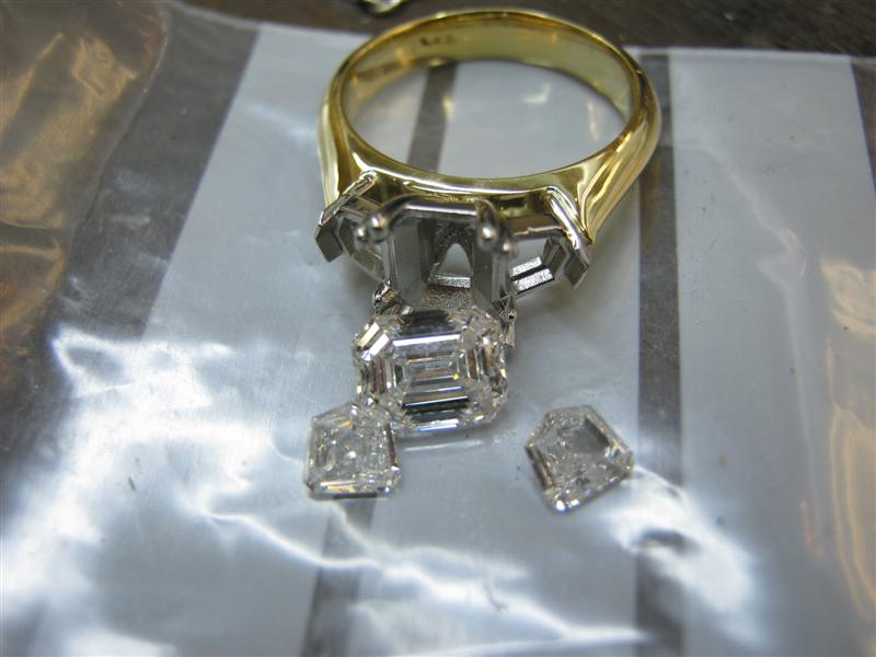
Hey.. cant all be dead possums and geometry nighmares.. have to do paying work from time to time!
http://www.hollowaydiamonds.com.au
Monday, 2 May 2011




Sunday, 1 May 2011


never trust a friend....
Niko sent me this pic.. of course the first thing I do is to make fun of him.. then model the fishook, then post it everywhere I can!


Saturday, 30 April 2011


Thursday, 28 April 2011
Tuesday, 26 April 2011


Sunday, 24 April 2011
Dead Possum!
and sometimes you model stuff that just makes you go.. WTF???
(lol, this is actually a mock up of a model in tsplines i did for someone i know.. jsut for kicks, but it supposed to be a dead opossum.. New Zealanders....)

(lol, this is actually a mock up of a model in tsplines i did for someone i know.. jsut for kicks, but it supposed to be a dead opossum.. New Zealanders....)

quadball doggy....

dont ask.. moddeling organic stuff is still new to me... this started out life as a quadball.. The remnants of which are left in the throat area ;)
(Undigested cat???)
Friday, 22 April 2011
Triple Dodecahedron model..
I did a nurbs dodecahedron Frabjous model some time ago.. figured I would give Tsplines a go at it as well...
Here is the old original model I did.

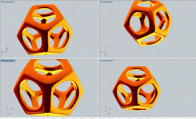


Here is the old original model I did.

And this is the Tsplines version, starting at the polygonal dodecahedron
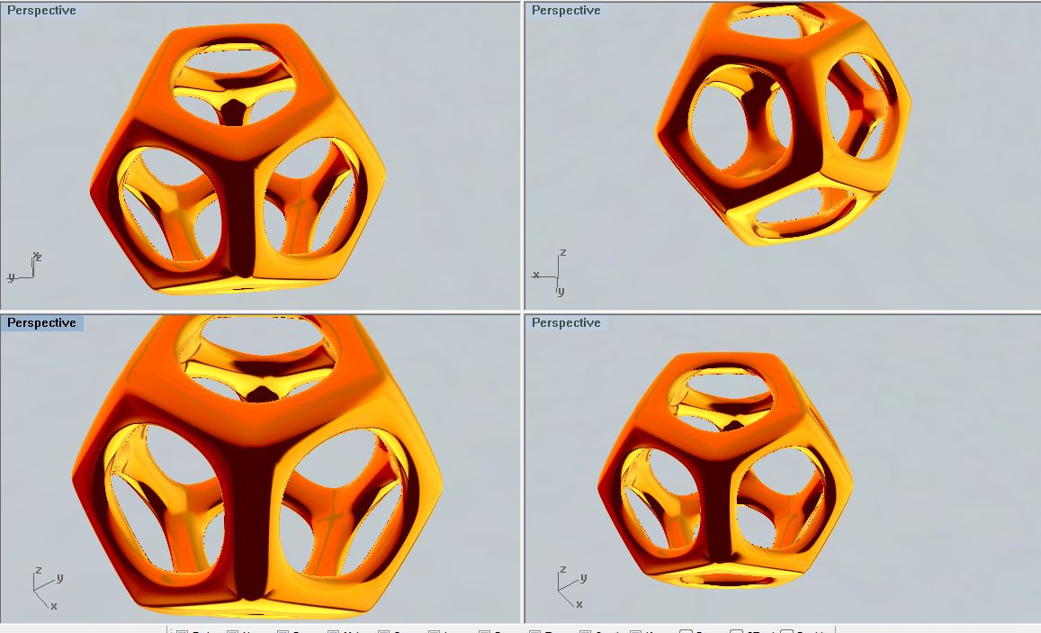
then the dual inner and outter triangle dodecahedron merge at their intersection points

and then finally the two together..


Wednesday, 20 April 2011
Sunday, 17 April 2011


Saturday, 16 April 2011
RhinoCam fully 2D puzzle bangle..
I am cutting this for someone else, its hardly an earth shattering design and i could have just done it as autoflip and rotary.. but.. I figured, what would be the most difficult way for me to do this..
Figure out the curves.. and cut the entire job as a 2d profiling and pocketing operation..
2 things i learned..
1: 2d work is trickier than it looks
2: In 2d this job will take 47mins @ 400mm/min.. in autoflip+rotary i was looking at 7 hours...
(it actually took 22 minutes to cut at +-900mm/min average velocity)


Figure out the curves.. and cut the entire job as a 2d profiling and pocketing operation..
2 things i learned..
1: 2d work is trickier than it looks
2: In 2d this job will take 47mins @ 400mm/min.. in autoflip+rotary i was looking at 7 hours...
(it actually took 22 minutes to cut at +-900mm/min average velocity)
Minitech / 123WaxRing Setup and Usage
I have long been enamoured by the fixture from Lex at DeskProto and after some discussion he happily provided me with a unit for testing. I have copied this post from our old forum where more in depth information is available.
I locked the fixture into my Sherline rotary and the time arrived to dial this sucker in!
The fixture relies on a perfect A and Z and X setup, Y and Z should both already be setup before you even set this fixture up since you will be locking into your rotary unit and would have this dialled in.
Lets get to it!
1: Finding perfect A... easy! roll the whole unit in A against a table square on your mill table, set your jog to 10% and slowly roll until no light is visible between the square blade and the fixtures top surface.

2: Click in the A DRO in Mach and type in 90 (or 270 depending on which side you setup the fixture table) then run the command G0A0. Simple - A is now perfectly flat to the spindle and A is now set :)
.JPG)
3: Time to setup X.. this too is pretty easily done, but make sure you are 100% carefull in this step, the 123waxringWizard software relies on X heavily, even a minor misalignment here will be amplified in your final model.. measure twice, cut once. To setup X drive the back of a 3.17 (1/8th) cutter up to the very edge of the fixture like below, CAREFULLY, set your jog speed right down when you get closer. when you are touching the fixture zero out X and drive directly upwards in Z away from the fixture, now time to correct our tooltip width, run the command G0X-1.585 then rezero X. Thats it for X.
.JPG)
4: these images are merely the way that I verified my Y before cutting, I am including them because all thing swith movable parts are subject to tolerances so screwing the fixture into its Sherline adapter may introduce errors, and even tho they are minor in most case its good to know how to look for them. Basically i drove my cutter to the very edge of each pin in Y and check the Mach DRO for position in Y on either pin, these should be virtually the same number only different in positive/negative assignment. Y verified!
.JPG)
.JPG)
.JPG)
.JPG)
5: Time to cut.. The software would have told you what thickness disk to use, lock it in the fixture with the chosen cutter in place and probed.
The first path will complete with half the disk cut away to reveal one side of the ring.
.JPG)
.JPG)
Turn the disk over and lock it back in. Cut the second path, you should be left with a well aligned flip cut wax, ready for the final rotary pass.
.JPG)
Lock it onto the rotary pins and lets finish this up!
.JPG)
.JPG)
And we are done!
Thank you for taking some time to read through this pictorial :)
.JPG)
.JPG)
Regards
Chris Botha
I locked the fixture into my Sherline rotary and the time arrived to dial this sucker in!
The fixture relies on a perfect A and Z and X setup, Y and Z should both already be setup before you even set this fixture up since you will be locking into your rotary unit and would have this dialled in.
Lets get to it!
1: Finding perfect A... easy! roll the whole unit in A against a table square on your mill table, set your jog to 10% and slowly roll until no light is visible between the square blade and the fixtures top surface.
2: Click in the A DRO in Mach and type in 90 (or 270 depending on which side you setup the fixture table) then run the command G0A0. Simple - A is now perfectly flat to the spindle and A is now set :)
3: Time to setup X.. this too is pretty easily done, but make sure you are 100% carefull in this step, the 123waxringWizard software relies on X heavily, even a minor misalignment here will be amplified in your final model.. measure twice, cut once. To setup X drive the back of a 3.17 (1/8th) cutter up to the very edge of the fixture like below, CAREFULLY, set your jog speed right down when you get closer. when you are touching the fixture zero out X and drive directly upwards in Z away from the fixture, now time to correct our tooltip width, run the command G0X-1.585 then rezero X. Thats it for X.
4: these images are merely the way that I verified my Y before cutting, I am including them because all thing swith movable parts are subject to tolerances so screwing the fixture into its Sherline adapter may introduce errors, and even tho they are minor in most case its good to know how to look for them. Basically i drove my cutter to the very edge of each pin in Y and check the Mach DRO for position in Y on either pin, these should be virtually the same number only different in positive/negative assignment. Y verified!
5: Time to cut.. The software would have told you what thickness disk to use, lock it in the fixture with the chosen cutter in place and probed.
The first path will complete with half the disk cut away to reveal one side of the ring.
Turn the disk over and lock it back in. Cut the second path, you should be left with a well aligned flip cut wax, ready for the final rotary pass.
Lock it onto the rotary pins and lets finish this up!
And we are done!
Thank you for taking some time to read through this pictorial :)
Regards
Chris Botha
Subscribe to:
Posts (Atom)